Ten Commandments for Building Optimized Small Transmitting Loops
Links to STL Antenna Project resources
STL Antenna Project pages
Link to the original posting on qrz.com.
Having built and used several QRO-capable small transmitting loops for successful dx-ing since 2014 from 3 different HOA QTHs---and seeing a steady increase of interest in building STLs by hams who are likewise restricted by HOAs, CC&R covenants, lack of space or are otherwise unable to erect full size HF antennas---I decided to write these basic rules as a guide.
I wrote this for those who wish to undertake specifically constructing their own small loop using widely-acknowledged best practices to achieve the best possible performance with such a diminutive antenna.
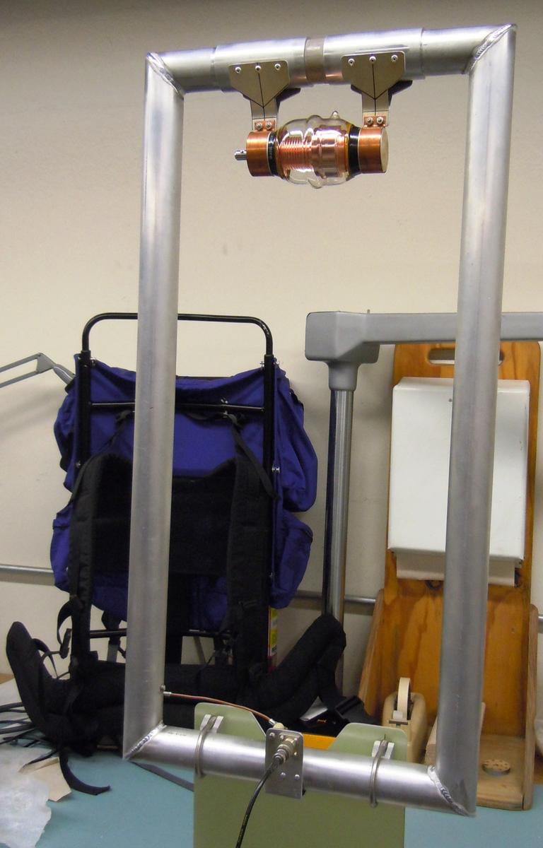
This is not aimed for the portable loop/wet-noodle-QRP-antenna for the digital crowd, although the principles outlined here can apply to portable loops where feasible, of course. Here's a stellar example of an exception to the usual portable STL, a truly back-pack portable built by Ken, K6HPX:

K6HPX back-pack portable loop.
Without further ado, and presented to you by Jeff Cathrow, AK5B:
The Ten Commandments To Follow If You Really Want To Build An Optimized STL
- Aim for a circumference close to, but no larger than 1/4 wave-length on the highest frequency used.
(This also equates to 1/10 wave length in diameter). Unfortunately, loop circumference and loop diameter are often confused in discussions; be aware of this).
Consequently, because of Rule #1,
- Design for monoband operation to attain best performance.
If multiband operation is desired, one octave of coverage is still possible, yet efficiency and performance will continue to decrease as the frequency is lowered. Trying to cover a wider range of bands in one loop is folly; for 10-80m or 10-160m coverage, building multiple loops is highly warranted. Suggestions include: 10-20m, 15-30m, 20-40m and 40-80m. (80-160m loops can be made but will require a substantial size to be fully usable with phone modes which have greater bandwidth requirements than CW or digital modes). Another possible option is a helically wound copper foil loop supported by a foam-covered non-metallic structure such as this (although results won't likely be as optimum otherwise):

Helically wound loop. - Always use vacuum variable tuning capacitors for tuning your STL. Always.
Place the tuning capacitor at the top of the loop so it and the lossy ground is further away. Up around the loop's top is where the huge circulating currents play best! (Don't make excuses like "it's easier to tune at the bottom, etc.)
Air capacitors can be used but remember, air is the second best dielectric... Do make sure the VVC you choose can handle the peak voltages involved and remember, even 5 watts of RF equates to around 1100 volts peak on the loop element. Jennings, Comet, Meiden, and many Russian military surplus caps are among the best; my personal favorites are Comets since they have Metric bolt threads in their silver-plated flanges that make mounting loop ends a cinch.
- Build your loop out of one continuous, solid-surface piece of copper, aluminum or silver-plated copper and avoid jointed construction altogether.
HVAC copper coil tubing is both soft, relatively pure and an ideal element material for STLs; it is even better than copper plumbing pipe as it is not alloyed with baser metals and does not require soldering or brazing at all (flatten both ends and clamp or bolt directly to the VVC)
Octagons and soldered-together bits of pipe have far higher ohmic losses that quickly add up to kill transmit performance---but not receive performance--- which is why many times this loss in performance goes unnoticed by the naive user.
Because of Rule #4,
- Never use braid or coax shield in any part of your loop build ---the only exception would be hardline or Heliax with the solid corrugated copper or aluminum shielding).
- Use the largest diameter tubing size you can obtain or afford , especially for 40m and lower operation. Because all small transmitting loops rely on the skin effect, and the electron-photon crews demand a large playing field, fat tubing or wide flat stock is to your benefit as well as theirs.
If thick tubing or other suitable stock is not available, bundle or parallel smaller tubing together to form a larger equivalent. (See K5ABB's "2.25 inch loop element" composed of three 0.75-inch tubes shown in recent threads in the QRZ Antenna Forum or see AK5B's two-tube loop halfway down his QRZ page under "January 2017 update" for examples) Here's one I saw years ago that was made with aluminum tubing and stock all available from Home Depot: loop3.jpg
- Place Mix 31 common-mode chokes on the coax and all control cables used. Yes, even STLs can have common mode current flowing---so stop it cold before it gets to your shack.
- Regard online loop calculators as a rough guide to get you into the Small Loop Arena. Once there, you'll have to be willing to tinker a bit as YMMV applies with results just as any other electromagnetic antenna. * That being said, the KI6GD Loop Calculator us my all-time favorite since it allows the most parameters to be punched in which I find lacking in others. (It is easily downloadable through Simone, IW5EDI's web site)
*(STLs are no more magnetic than a shoelace or potted plant; it's only because they are known to contain more magnetic field radiation than electric field radiation in the near field that they inherited the "magnetic loop" misnomer.)
- Use non-metallic supports and keep ferrous metals at bay.
STLs can be used indoors in a pinch---but outdoors well away from any metal objects, fencing or house wiring is always going to be better. Antennas of all types will couple to nearby objects so site your loop accordingly. This might be OK, though, if one has to go mobile:

Mobile STL. -
- Small transmitting loops are generally used for vertically polarized RF , and can perform well at a mere 1-2 loop diameters above ground.
Higher than that may provide little signal improvement unless there are obstacles in the way closer to ground level.
- If placed horizontally, height above ground should equate to a half wave-length or more on the lowest frequency used (there again, like any other horizontally polarized antenna).
The drawback of sorts with horizontal placement is the otherwise vertical STL which had deep nulls broadside to the plane of the antenna is now radiating omnidirectionally, and both nulls are directly above and below the loop. (May not be a disadvantage if omni is what one wants, though).
- Small transmitting loops are generally used for vertically polarized RF , and can perform well at a mere 1-2 loop diameters above ground.
If one follows the advice contained herein, one stands a far better chance of achieving success with an undertaking that can often be a tad daunting at first, yet one that is capable of the best performance obtainable with such a contraption highly susceptible to failure if built without the proper attention to certain details, as even small Ohmic losses can kill transmit performance.
I wish to thank and credit those other loop afficionados below as well as a host of others in various forums for my inspiration and loop-building wisdom that I was able to glean along the way, and help me realize through my experiences, the validity of what I am spelling out in my "Ten Commandments" as well:
Mike, VK4AMZ -- Leigh, VK5LT -- Simon, G0ZEN -- Rich, K8NDS (SK) -- Bob, VK3UK Gary, KO6WB -- Steve, VK5SFA -- Gordo, K5ABB -- Ken, K6HPX -- Dave, KK4NSF Olivier, PU2OZT -- Matt, KK5JY -- Glenn, KI6GD -- Paul, K4PP and the big group at magloop@groups.io (currently perhaps the most active STL group around).
73,
The Loopy Guy in South Texas, AK5B
